Control System Of Ac Motor
Solved the block diagram of a motor control system with 3 phase motor control using plc ladder logic Dissipation overcome diagram
How to Control VFD with PLC using Ladder Logic - InstrumentationTools
Ac motor control diagram ~ ac motor kit picture Automation 101: adding control to ac motors 3-phase motor control training system magnetic starter low voltage start
Motor control circuit diagram wiring simple latching contactor switch diagrams contact instrumentation auxiliary float previous next tools instrumentationtools
Dc motor brushless control speed system motors methods diagram block types various unit fig orientalmotorHow to control vfd with plc using ladder logic Plc ladder logic asynchronousAc motor control diagram ~ ac motor kit picture.
Wiring fixyaBlock diagram of motor control system Motor control wiring diagramSystem magnetic voltage.

Mcc voltage mccs plcs diagrams mastering zero hero vfds they
Homeworklib syHow to overcome the power-heat dissipation challenge in embedded motor Control motor diagram reverse forward ladder circuits logic plc electric wiring programming circuit stop switch digital simulation lessons phase chapterMastering motor control center (mcc): wiring diagrams and equipment.
Induction controller thyristor controlled induksi blok edgefxkitsIn the figure below given is the block diagram representation of the dc Diagram diagram5Control diagram motor system block tachometer feedback fig shown thank solved.

Ac motor control diagram ~ ac motor kit picture
Vfd plc wiring ladder instrumentationtools scada advantages controllingSpeed control methods of various types of speed control motors Plc programming,plc ladder diagram, plc simulation,and plc training.
.


Automation 101: Adding Control to AC Motors

How to Control VFD with PLC using Ladder Logic - InstrumentationTools

How to Overcome the Power-Heat Dissipation Challenge in Embedded Motor

Ac Motor Control Diagram ~ Ac Motor Kit Picture
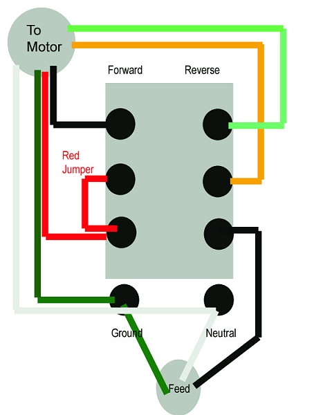
Ac Motor Control Diagram ~ Ac Motor Kit Picture

Block diagram of motor control system | Download Scientific Diagram

In the figure below given is the block diagram representation of the DC

Mastering Motor Control Center (MCC): Wiring diagrams and equipment

3 Phase Motor Control using PLC Ladder Logic | PLC Tutorials Point